CSC 480 Lab #9
"This is the end..." Lab
Purpose
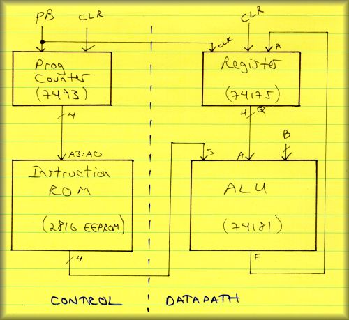
Design a simple computer consisting of:- a control unit with program counter and instruction ROM, and
- a datapath unit with ALU and register
Components used
We will be using:- 7493 binary counter
- 2816 EEPROM
- 74181 Arithmetic Logic Unit
- 74175 quad D flipflops
Pinouts are attached.
Lab Problems
OK, let's build a small computer with a small instruction set. Small is a definite over-statement here, BTW. Here is a block diagram of the system you will be building:
Once complete, the system has four inputs:
- Counter clear
- Register clear
- Clock (to the counter and flipflops)
- B input to the ALU (4 bits)
The outputs will be:
- The count (from the program counter) will be displayed in the seven segment display
- The current 4-bit instruction will be shown on the LED's
- The current output of the register (Q outputs of the 74175 flipflops) will also be shown on the LED's
Once your computer is built, there are two problems to complete.
Part 1. Execute Prof Bill's ROM program
Hard-code the following settings for this problem:
- Tie the ALU mode input to 1 for logic functions
- Tie Cn to high for no carry-in
- Clear the A register before starting
- Set the B inputs to the ALU to 0101
Place the following instructions in your EEPROM, excute the program and complete the table.
| PC
(octal) |
Instruction | ALU Func
(F=) |
A | B | "Next A" |
| 00 | 0000 | A' | 0000 | 0101 | |
| 01 | 1010 | B | 0101 | ||
| 02 | 0110 | A xor B | 0101 | ||
| 03 | 0001 | (A+B)' | 0101 | ||
| 04 | 1110 | A+B | 0101 | ||
| 05 | 0011 | 0 | 0101 | ||
| 06 | 1101 | A+B' | 0101 | ||
| 07 | 0010 | A'B | 0101 | ||
| 10 | 1000 | A'+B | 0101 | ||
| 11 | 0101 | B' | 0101 | ||
| 12 | 1100 | 1 | 0101 | ||
| 13 | 0100 | (AB)' | 0101 | ||
| 14 | 1111 | A | 0101 | ||
| 15 | 1011 | AB | 0101 | ||
| 16 | 1001 | (A xor B)' | 0101 | ||
| 17 | 0011 | 0 | 0101 |
In the table, A and "Next A" are each the output of your A register or flipflops. A is before the clock pulse, and "Next A" is the value after the clock pulse. The value of "Next A" is then used as A in the next instruction.
For part 1, please turn in the following deliverables:
- Please draw a more detailed circuit diagram of your computer and notes on the steps you took to build your machine
- Complete the table above (on a separate piece of paper please)
- Show me your computer executing the instructions above
Hints and such
This is our largest design in lab. It will require your patience and discipline. Some general thoughts before starting:
- I setup busses for power and ground (power on the outside, ground inside) as a first step. If you don't know how to do this, see me. We're tying a lot of inputs to logic one and zero and this was essential in reducing congestion.
- My component order on the board was (left to right) 7493 Counter, 2816 EEPROM, 74181 ALU, 74175 D flipflops.
- I took the same approach I would programming a large system. Complete each subsystem, verify that it works and then move on. As a last step, complete and test your system.
Here are the major steps I took in completing the lab... these are not required steps, but rather just a cheat sheet:
STEP 1: Hookup and program the 2816 EEPROM
- Connect the address pins A3:A0 to switches S7:S4
- Connect the I/O pins IO3:IO0 to switches S3:S0
- Ground all higher, unused address pins and I/O pins
- Connect all the enable inputs CE', WE' and OE' per last week's lab... writing to the EEPROM when pressing the pulse button
- Connect I/O pins IO3:IO0 to LED's
- After programming the EEPROM, disconnect the I/O inputs and verify that your instructions were properly written
- Once you're satisfied that the EEPROM has your instructions, disconnect WE' and OE' from the pulse button. Place the EEPROM in read mode for the rest of the lab
Move on to step 2 once you are satisfied that your EEPROM is correctly programmed.
STEP 2: Hookup the 7493 Counter
- Connect the counter's reset inputs to a switch, so that you can set the counter to 0
- Connect the counter's "Input A" to a pulse button
- Connect QA to "Input B" to get a 16 count
- Connect the counter outputs QD:QA to EEPROM address inputs A3:A0. (Disconnect the switches to these inputs, if you haven't already)
- Also connect the counter outputs to the seven segment display as in the previous lab
Move on to step 3 once you can reset your counter to zero and correctly step through EEPROM instructions 0 through 15.
STEP 3: Hookup the 74181 ALU
First off, use active high inputs as we did in lab. Go:
- Connect the EEPROM instruction outputs IO3:IO0 to the ALU's function select inputs S3:S0
- For part 1, we hard-coded the mode and carry-in inputs to 1
- Connect switches S3:S0 to data inputs A3:A0 of the ALU
- Connect B3:B0 inputs of the ALU to power and ground so that B equals 0101, per the lab
- Connect the ALU output pins F3:F0 to LED's L7:L4
With most of your system setup, you can verify that your instructions correctly exercise the ALU by setting the A value with your switches and observing the outputs on the LED's.
STEP 4: Hookup the 74175 D flipflops
- Connect the ALU outputs F3:F0 to D inputs 4D:1D
- Connect the flipflop outputs 4Q:1Q to LED's L7:L4
- Connect the flipflops CLR input to a switch (it's active low remember)
- The flipflop is positive-edge so connect to the positive-edge pulse button that you are also using for the counter
Almost there... before starting, clear your counter and your flipflops to zero.
STEP 5: Close the loop
Complete the system and run your program...
- Connect the flipflops outputs 4Q:1Q to the ALU's A inputs A3:A0 (disconnect the switches that you were using) to close your system
Go! Show me your program running (correctly, eh) before moving on.