Purpose
| Finite state machine design |
Components used
| 74175 quad D flipflops with clear |
And others, of course. You should have the diagrams for other logic gates in your previous lab handouts. If not, just ask and we'll look it up.
Lab Procedure
Le basics:
| For your safety... unplug the logic box while you are working on it! | |
| For the health and safety of your chips... watch your power and ground inputs! |
Lab Problems
This lab focuses on sequential circuit design using finite state machines... described in Chapter 6 of our text.
For your consideration:
| How will you start your machines? In other words, how will you place them in their initial state? I might suggest using the reset inputs on your D flipflops. | |
| When testing your machines, exercise all transitions in the state diagram... as proof that your machine works. | |
| Use the pulse buttons for you clock input and the switches for data inputs. But, of course! |
1. FSM design, starting with a table
Design a sequential circuit (using D flipflops) that satisfies the following state table:
Present State
Input Next State
Output A B X A B Y 0 0 0 0 0 0 0 0 1 0 1 0 0 1 0 0 0 1 0 1 1 1 1 0 1 0 0 0 0 1 1 0 1 1 0 0 1 1 0 0 0 1 1 1 1 1 0 0 Please draw your state diagram, your logic design work to get minimized flipflop equations, and your circuit diagram (with switches, pins, etc labeled).
2. FSM design, starting with a diagram
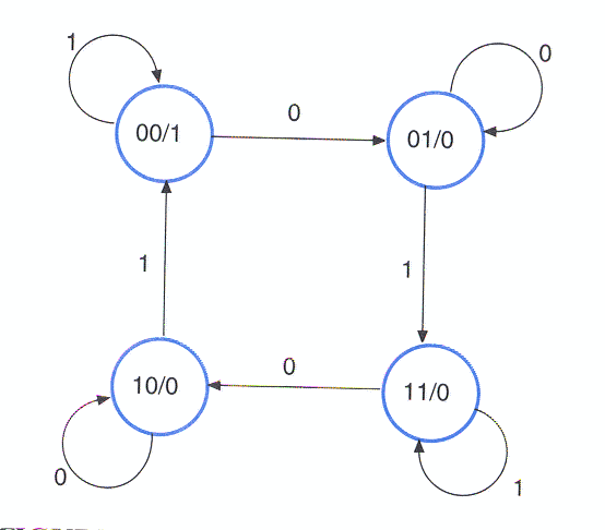
Design a sequential circuit (using D flipflops) that satisfies the following state diagram:
Please draw your state diagram, your logic design work to get minimized flipflop equations, and your circuit diagram (with switches, pins, etc labeled).
Note: you should be able to build this guy with a couple nand chips, eh.
3. FSM Design, a word problem
Design a traffic light controller. Your design should have:
an input, Tick - when true, the traffic light should cycle to the next logical light (or state) and when false, the light should stay at its current position (or state)
an input, ER - when true, the ER (Emergency Red) means that the next light should be Red and when false, ER is ignored
3 states: Red, Yellow, Green
3 outputs: Red, Yellow, Green - one each for turning on each bulb in the traffic light thingie
First, do a symbolic state table. Is this a Mealy or Moore machine?
Then, STOP!
I want to see your table, and then, with a little teacher-ly coordination, each lab group will use a different state assignment. We'll compare results at the end to see whose state assignment came out the "nicest".
Then, build it, and show it to me.
Deliverables
The usual... let me see your masterpiece when it's ready.
