
Nice definition from the book:
"A multiplexer is a combinational circuit that selects
binary information from one of many input lines
and directs the information to a single output line."
Block diagram:
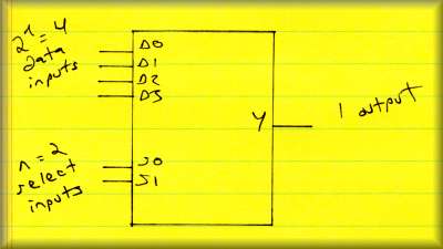
| n Select inputs | |
| m (<= 2n) data inputs... treated as minterms of the select inputs | |
| 1 output | |
| One of the data inputs passed through to the output, based in the value of the select inputs |
The implementation is easy.
| Minterms of the data inputs can be built with AND, OR network | |
| Select bits fed (addressed) into the AND gates to choose the proper data |
Minterm generators... similar to decoders
VERY useful in simplifying logic design
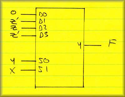
Example:
F(x, y, z) = SUM( 0, 3, 5, 6)
Implement this with a 4-to-1 mux...
| Assign the high-order bits (x and y) to the select inputs | |
| Assign the data inputs according to the truth table, each xy row pair |
| xyz | F | Y output |
| 000 | 0 | |
| 001 | 0 | D0 = 0 |
| 010 | 0 | |
| 011 | 1 | D1 = z' |
| 100 | 0 | |
| 101 | 1 | D2 = z |
| 110 | 1 | |
| 111 | 0 | D3 = z' |
Circuit diagram:
Same as the decoder... so often called a Decoder/Demux