Block diagram:
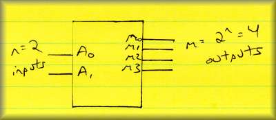
| n inputs | |
| m (<= 2n) outputs | |
| Each output is a minterm of n... decoder is a "minterm generator" | |
| Implementation is straightforward: SOP form built directly with AND, OR gates | |
| Often an enable bit is added to turn the decoder on/off |
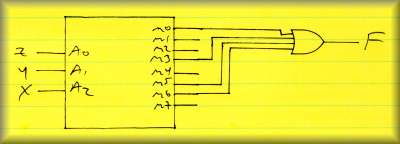
Use decoders as a quick and dirty way to implement functions... example:
F = SUM( m0, m3, m5, m6)
Implement this with a 3-to-8 decoder... the outputs are the minterms, you supply the or gate.
Building the decoder with NAND gates, inverts the outputs... circuit diagram for a 2-to-4 decoder bult with NAND gates:
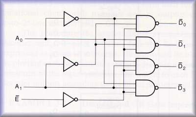
Figure 3-14, p. 113
What's the point?
| Cheaper to build with NAND gates in many technologies | |
| What's the complement of m0 (minterm zero)? It's M0 (maxterm zero), of course. | |
| So, this decoder can be used to implement POS functions |
POS example:
F = SUM( m1, m4, m6)
F' = SUM( m0, m2, m3, m5, m7)
F' = PRODUCT( M1, M4, M6)
Using F' we can invert the POS maxterms result from our decoder with NAND gates, giving us the following circuit:
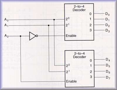
You can combine smaller decoders to build larger ones.
Example: Build a 3-to-8 decoder using two 2-to-4 decoders with enables
Figure 3-15, p. 114
| Lower-order bits (A0, A1) are the data bits | |
| High-order bit (A2) selects the low-order minterms to be used |